Introduction#
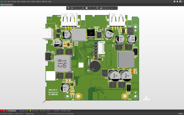
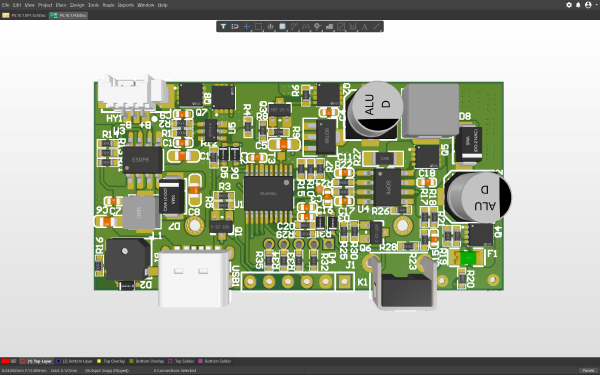
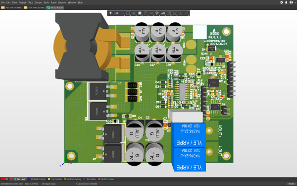
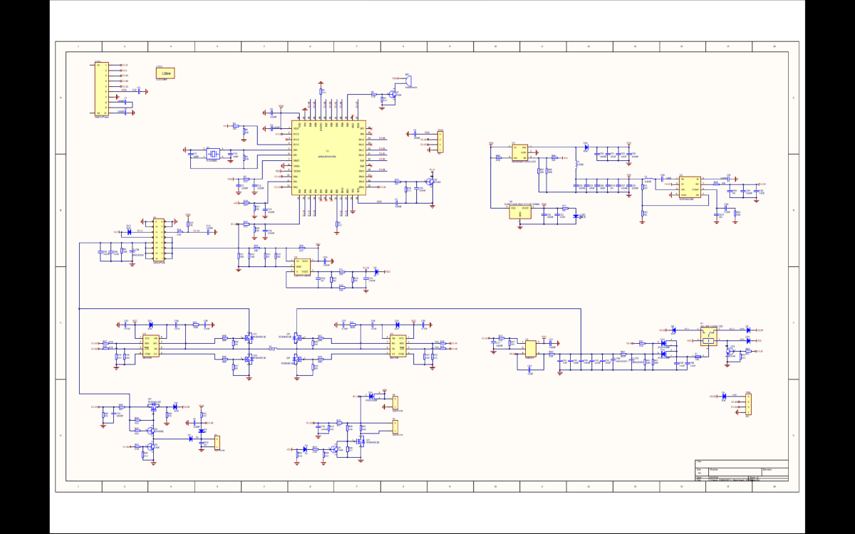
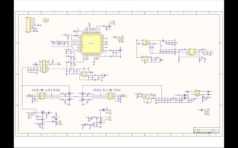
The Multi-Source Input Supercapacitor Car Jump Starter Controller is a high-performance emergency car jump starter based on a bidirectional DC-DC H-bridge Buck-Boost topology. Using a supercapacitor module as its core energy storage unit, the system achieves highly efficient energy storage and instantaneous discharge through precision hardware circuits. The device integrates automatic switching logic for three input sources: car battery, USB, and DC adapter, utilizing a full-bridge circuit to achieve bidirectional power flow.
Hardware Showcase#
Software Showcase#
Functional Specifications#
1. Core Electrical Specifications and H-Bridge Functions#
Bidirectional DC-DC H-Bridge Buck-Boost System:
- Topology Structure: Utilizes a full-bridge circuit composed of 4 high-power MOSFETs, combined with a high-frequency inductor to form a synchronous rectification Buck-Boost converter.
Smart Charging Strategy:
- Buck Mode: When the input voltage (e.g., 12V car battery or 19V DC adapter) is higher than the capacitor bank voltage, it automatically steps down the voltage for constant-current charging.
- Boost Mode: When using a 5V USB input, it automatically steps up the voltage to the required level for the capacitor bank.
- Stable Voltage Discharge: During engine cranking, it maintains a stable output voltage to prevent voltage drops that could cause the ECU to reset.
Multi-Source Input Specifications:
- Car Battery Input: Wide voltage input (6V-24V), supporting energy harvesting and boosting from a dead car battery.
- DC Input: Supports 12V-20V adapter input for high-current fast charging.
- USB Input: Supports 5V/2A-3A input, compatible with power banks.
2. OLED Display and Human-Machine Interaction System#
Equipped with a customized OLED screen, the device uses the MCU to collect real-time data from various sensors, displaying key information in graphical or digital formats:
Main Interface Layout:
- Input Source Identification Icon: The top of the screen dynamically displays the icon of the currently active input channel (⚡ for car battery input, 🔌 for DC input, 🔋 for USB input).
Real-Time Input Parameter Area:
- Input Voltage: Accurately displays the real-time voltage value of the current input terminal.
- Input Current: Refreshes the current charging current in real time, allowing users to intuitively understand the charging speed.
Core Energy Storage Status Area:
- Capacitor Voltage: Displays the terminal voltage of the supercapacitor bank in large text, which is the key indicator for determining jump-start readiness.
- Charging Progress Bar: A graphical progress bar intuitively displays the capacitor’s charge percentage (0%-100%).
Output / Start Status: When connected to the car for starting, the display switches to show the output voltage and the instantaneous starting current.
Interaction Logic:
- Power-On Self-Test: Upon power-up, the screen performs a full-pixel self-test before entering the main interface.
- State Refresh Rate: Voltage and current data refresh rate is ≥10Hz, ensuring smooth numerical transitions without lag.
- Exception Pop-ups: When a fault is detected, a red warning box (e.g., “OVER TEMP”, “SHORT CIRCUIT”) pops up in the center of the screen.
3. Hardware Architecture and Key Circuits#
Power Stage Drive Circuit: MOSFET Array: Selects low Rds(on) and high-voltage N-MOSFETs to build the H-bridge, paired with dedicated gate driver chips to ensure switching efficiency and thermal stability during high-current charging and discharging.
High-Frequency Magnetic Components: Employs low-loss alloy powder core inductors to withstand the high-frequency ripple current generated by the H-bridge, reducing heat generation.
Signal Acquisition and Feedback Loop:
- High-Precision Sampling: Precision shunts or Hall effect sensors are placed at the input, output, and capacitor terminals to feed analog signals into the MCU’s ADC ports, providing accurate data sources for the OLED display.
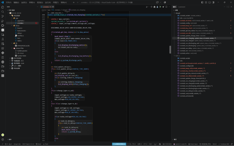
- Closed-Loop Control: Based on the acquired voltage and current data, the MCU dynamically adjusts the PWM duty cycle of the H-bridge via PID algorithms to achieve constant-current/constant-voltage charging and stable voltage output.
4. Safety Protection System#
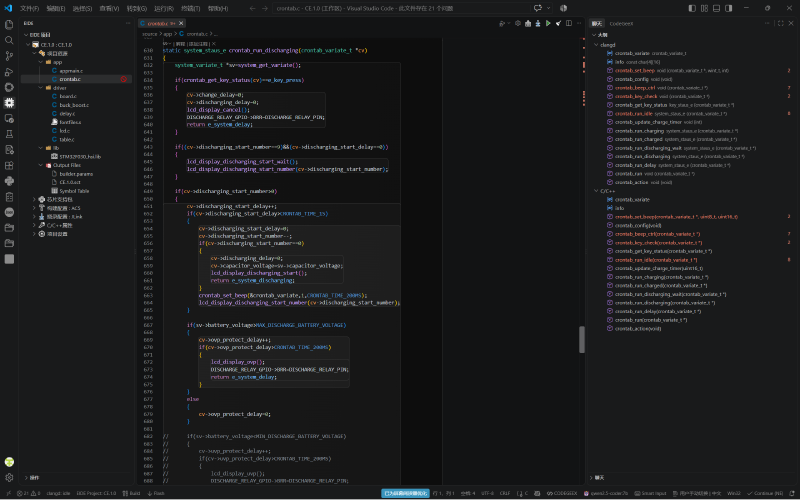
Short-Circuit Protection: Hardware-level comparators monitor the output current in real time. Once a short circuit (surge in current) is detected, all MOSFETs in the H-bridge are turned off within microseconds, and a “SHORT” warning is displayed on the OLED screen.
Reverse Polarity Protection: A high-power MOSFET reverse-polarity protection circuit is connected in series at the input terminal, utilizing the MOSFET’s body diode or independent control logic to prevent internal circuit damage if the battery clamps are connected incorrectly.
Over-Temperature Protection: NTC thermistors are attached next to power components. When the temperature of the H-bridge or inductor exceeds the threshold, the charging current is automatically reduced or the operation is halted, and the temperature reading is displayed on the screen.
Over-Voltage / Under-Voltage Protection: Real-time monitoring of the capacitor voltage prevents overcharging damage to the capacitors or over-discharging that could affect their lifespan.