Introduction#
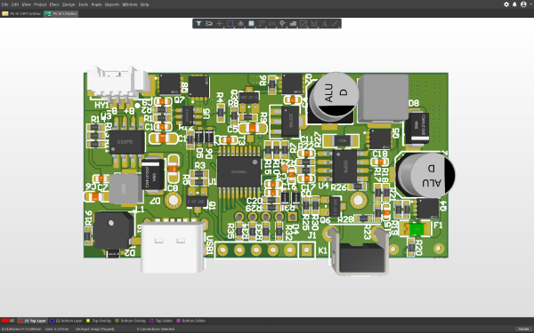
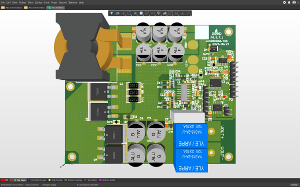
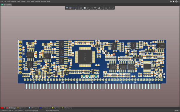
This controller is a smart power management device that integrates high-precision pulse discharge and charge management functions. Based on a high-performance MCU core, the system integrates a high-power MOSFET array and a precision pulse generation circuit. It supports dual modes of constant-current DC discharge and high-voltage pulse discharge, featuring comprehensive battery capacity monitoring, timing logic, and human-machine interaction. It can effectively discharge battery capacity while preventing over-discharge.
Hardware Showcase#
Software Showcase#
Functional Specifications#
1. Core Electrical Specifications#
Basic DC Discharge Mode:
- Load Characteristics: Constant current/constant power discharge, with an equivalent output voltage set to DC 8.0V.
- Continuous Discharge Current: 2.8A (Continuous stable operation).
High-Voltage Pulse Mode:
- Pulse Frequency: 2Hz.
- Duty Cycle: 10%.
- Peak Pulse Voltage: 18V.
- Current Characteristics: Average current of 0.36A, with a momentary peak current of up to 3.6A, used for battery plate activation or internal resistance testing.
Power Specifications:
- Total Power Limit: The system’s maximum thermal dissipation and output power are limited to 30W.
Battery Management Parameters:
- Discharge Cutoff Voltage: Single cell 2.9V (Precise detection to prevent over-discharge).
- Capacity Release Target: Ensures that 90% of the total battery capacity is released before the cutoff threshold is reached.
2. Hardware Architecture and Key Components#
Power Drive Stage:
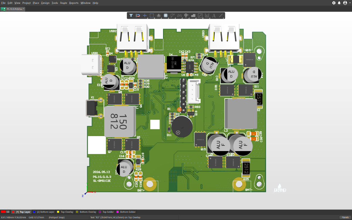
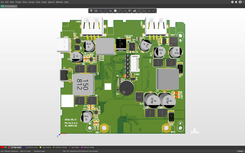
- High-Current MOSFET Array: Multiple high-power MOSFETs are onboard, operating in parallel to share the 2.8A continuous current and 3.6A pulse surge current, effectively reducing on-resistance and heat generation.
- Energy Storage and Filtering Inductors: Large shielded power inductors combined with solid-state capacitors are used to smooth the pulse current waveform, ensuring the stability of the 18V pulse and the purity of the DC output.
Main Control and Detection Unit:
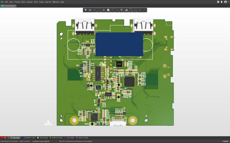
- MCU Controller: The core processing unit responsible for PWM pulse generation, ADC voltage sampling, and logical timing control.
- Buzzer: Located in the center of the board to provide an audible alert upon task completion.
Interface Layout:
- Battery Input Terminal: Located at the bottom of the board, featuring large solder pads or terminal blocks to support high-current input.
- USB Interfaces: Multiple USB ports are reserved at the top, potentially used for power supply or as output channels.
- Data Upload Reserved Area: The board reserves module mounting space and communication interfaces to support future IoT expansion.
3. Safety Protection System#
To ensure the safety of both the battery and the equipment, the controller incorporates multiple hardware and software protection mechanisms:
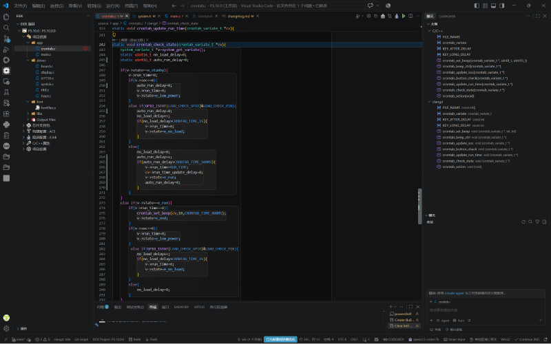
- No-Load Protection: The system features load detection functionality. Discharge is prohibited and the timer will not start if no load is connected, preventing operational errors.
- Over-Discharge Protection (UVLO): Real-time monitoring of cell voltage; the discharge circuit is immediately cut off once the 2.9V cutoff threshold is reached.
- Over-Current and Short-Circuit Protection: If the current abnormally exceeds the 3.6A peak or a short circuit occurs, the hardware circuit shuts down the MOSFETs within milliseconds.
- Thermal Protection: Monitors the temperature of power components to prevent overheating damage during full 30W load operation.
4. Human-Machine Interaction and Logic Control#
TFT Display Interaction:
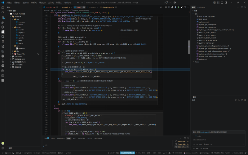
- Battery Level Display: Displays the remaining capacity percentage in 1% minimum increments.
- Status Indication: Clearly displays working states such as “Standby” (Ready) and “Finish” (End).
Timing Logic:
- Default Duration: A single operation cycle is set to 30 minutes.
- Non-Cumulative Timing: If stopped midway, restarting will initiate a new 30-minute cycle without accumulating the previous runtime.
Audio/Visual Alerts:
- Completion Reminder: After the 30-minute countdown ends, the buzzer emits ten intermittent “beeps” as a strong alert.
- Auto Power-Off: After the alert sounds finish, the system automatically enters a power-off or deep sleep state to save energy.
5. Expansion Features#
- Data Upload Module: Dedicated interfaces and physical mounting space are reserved to support external communication modules (such as 4G/NB-IoT/Wi-Fi).
- Data Logging: Capable of recording and uploading the device’s usage count and cumulative runtime to facilitate remote O&M and lifespan management.