Introduction#
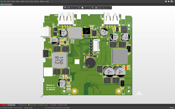
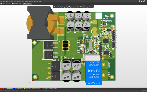
The Smart Pulse Power Supply is a portable smart power device specifically designed for coil driving. Based on a high-performance MCU core, the system integrates a boost drive circuit and precision pulse generation logic. It supports three adjustable levels of high-frequency, high-voltage pulse output, providing stable excitation energy for various coil loads through precise duty cycle and frequency control. Featuring a minimalist single-button and digital tube interaction design, along with a comprehensive battery management and safety protection system, it is ideal for driving and controlling electromagnets, micro vibrators, and various induction coils.
Hardware Showcase#
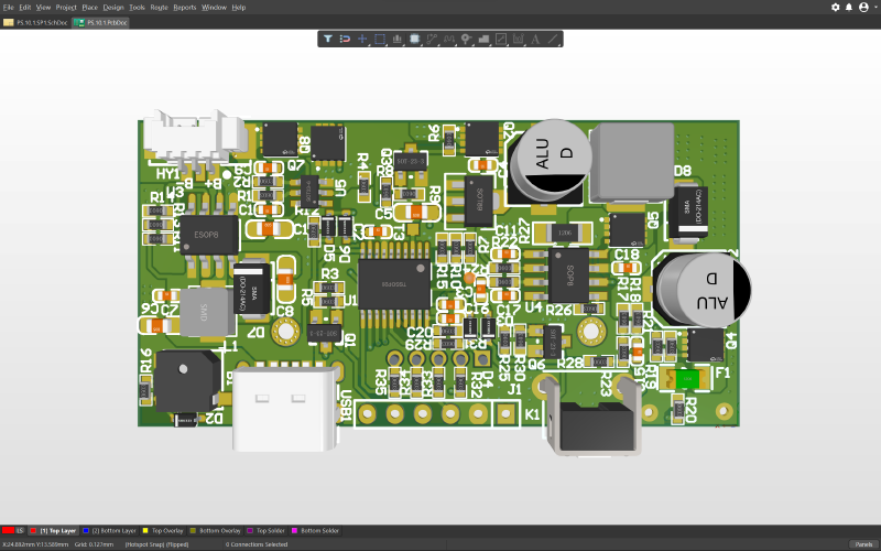
Software Showcase#
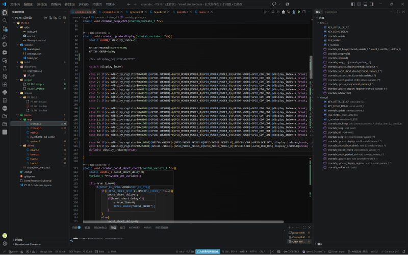
Functional Specifications#
1. Core Electrical Specifications#
Pulse Output Mode:
- Output Voltage: 24V (Generated by the internal boost circuit).
- Duty Cycle: Fixed at 20%.
- Current Characteristics: Average current of 0.1A, with a momentary peak current of 0.5A.
Frequency Levels:
- Level 1: 10Hz (Low-frequency, high-force drive).
- Level 2: 40Hz (Mid-frequency, balanced drive).
- Level 3: 80Hz (High-frequency, fast-response drive).
Power Management Parameters:
- Cell Discharge Cutoff Voltage: Single cell 2.9V (Precise detection to prevent over-discharge).
- Capacity Release Target: Ensures that 90% of the total battery capacity is released before the cutoff threshold is reached.
Charging Input:
- Interface Type: USB Type-C.
- Input Voltage: 5V DC.
2. Hardware Architecture and Key Components#
Power Drive Stage:
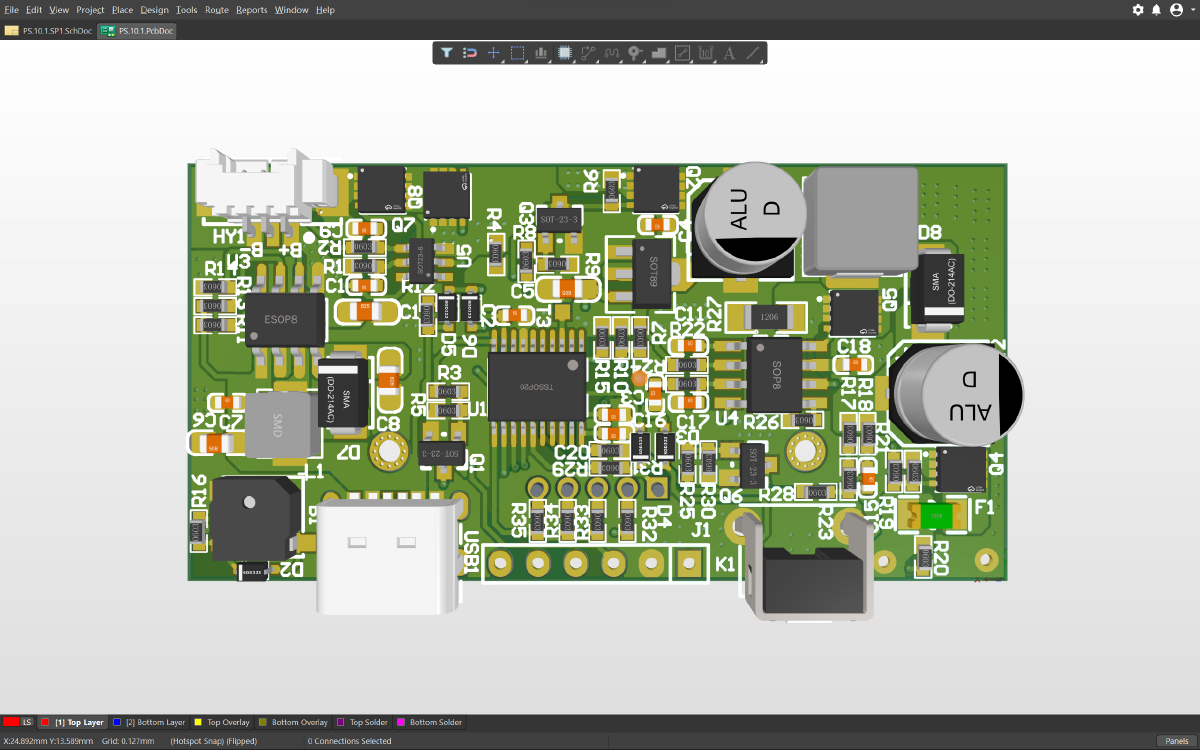
- Boost Inductor and MOSFET: A high-power shielded inductor combined with an N-MOSFET is onboard to build a BOOST step-up topology, boosting the battery voltage to 24V to drive the coil load.
- Output Interface: Wire soldering pads (Output Pads) are reserved for directly connecting the coil leads.
Main Control and Interaction Unit:
- MCU Controller: The core processing unit responsible for PWM waveform generation, button scanning, and digital tube dynamic scanning.
- Digital Tube Display: An onboard LED digital tube is used to intuitively display the remaining battery percentage and the current working level.
- Tactile Button: Located at the edge of the board for power on/off, level switching, and start/stop control.
Power Interfaces:
- USB Type-C Receptacle: Supports 5V charging input.
- Battery Connection Terminal: Connects to the lithium battery pack via soldering wires or terminal blocks.
3. Safety Protection System#
To ensure the safety of both the coil drive and the equipment, the controller incorporates multiple hardware and software protection mechanisms:
- Over-Discharge Protection (UVLO): Real-time monitoring of the cell voltage; the discharge circuit is immediately cut off and pulse output is stopped once the 2.9V cutoff threshold is reached.
- No-Load/Timeout Auto Power-Off: If the system is in a state of no output and no button operation for more than 5 seconds, it automatically enters power-off mode to prevent accidental battery depletion.
- Output Short-Circuit Protection: If a short circuit occurs at the 24V output terminal, the hardware circuit shuts down the MOSFET within milliseconds to prevent damage to the drive chip.
- Charging Protection: A built-in charge management chip prevents damage to the internal circuit from over-voltage or reverse connection during 5V input.
4. Human-Machine Interaction and Logic Control#
Button Operation Logic (Single Multi-function Button):
- Power On / Level Switching:
- 1st Short Press: Power on, default output at Level 1 (10Hz).
- 2nd Short Press: Switch to Level 2 (40Hz).
- 3rd Short Press: Switch to Level 3 (80Hz).
- Note: If the pulse is currently outputting, a short press cannot switch levels; the output must be stopped first.
Start/Stop Output:
- Long Press: Starts pulse output; if currently outputting, a long press will stop the output.
- Auto Sleep: The device automatically powers off after 5 seconds of no output and no button operation.
Display Interaction:
- Alternating Display: The screen cyclically alternates between displaying the remaining battery percentage and the current level number (1/2/3).
Timing Logic:
- Default Duration: A single operation cycle is set to 30 minutes.
- Non-Cumulative Timing: If stopped midway, restarting will initiate a new 30-minute cycle without accumulating the previous runtime.